

Section 2.2: Meshing process
Step 1: Create the first block
Use the command Create Block, 3D bounding box, and click apply to obtain the block in Fig. 2.10.
Step 2: Setting the periodicity
From the Mesh menu Global Mesh Setup, select Set up Periodicity, activate Define Periodicity, use Rotational Periodic Periodicity Type, select the method User defined by angle, insert 0 0 0 in Base, 0 0 1 in Axis and 51.428571 in Angle as is shown in Fig. 2.11
Step 3: Axis projection
Use the tool Associate Edge → Curve from the Blocking Associations menu and pick the edge over the axis and the axis curve.

Fig. 2.10 First block

Fig. 2.11 Setting the periodicity
Step 4: Define periodic vertices
In the Block menu, select Edit Block, Periodic Vertices and select pairs of vertices in the J direction picking first the one on the plane Y=0 as it is shown in Fig. 2.12. If the periodicity and the periodic vertices are properly defined you will see the periodic faces like in Fig. 2.13 right clicking on Faces from the Model Tree and selecting Periodic Faces.
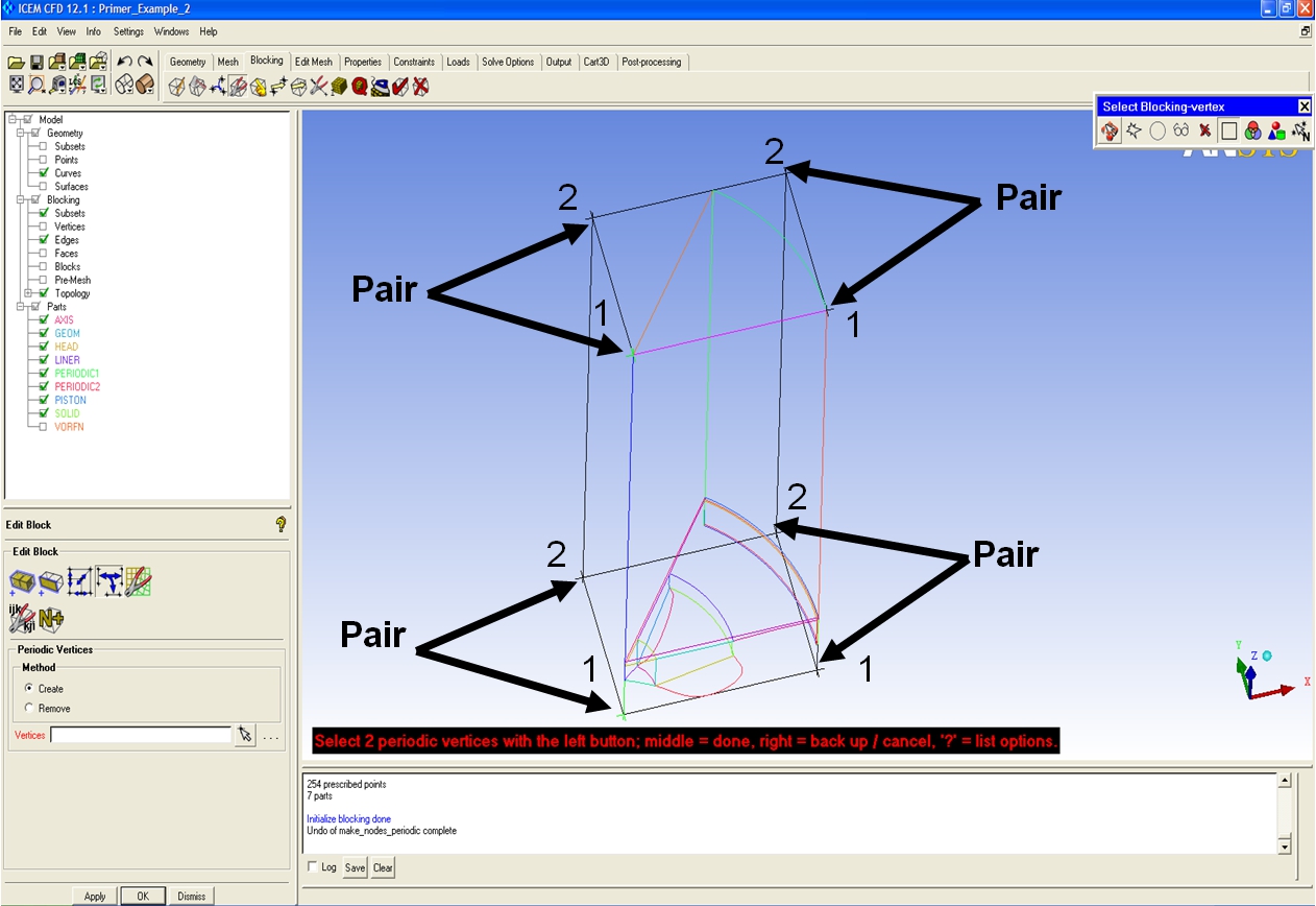
Fig. 2.12 Define periodic vertices
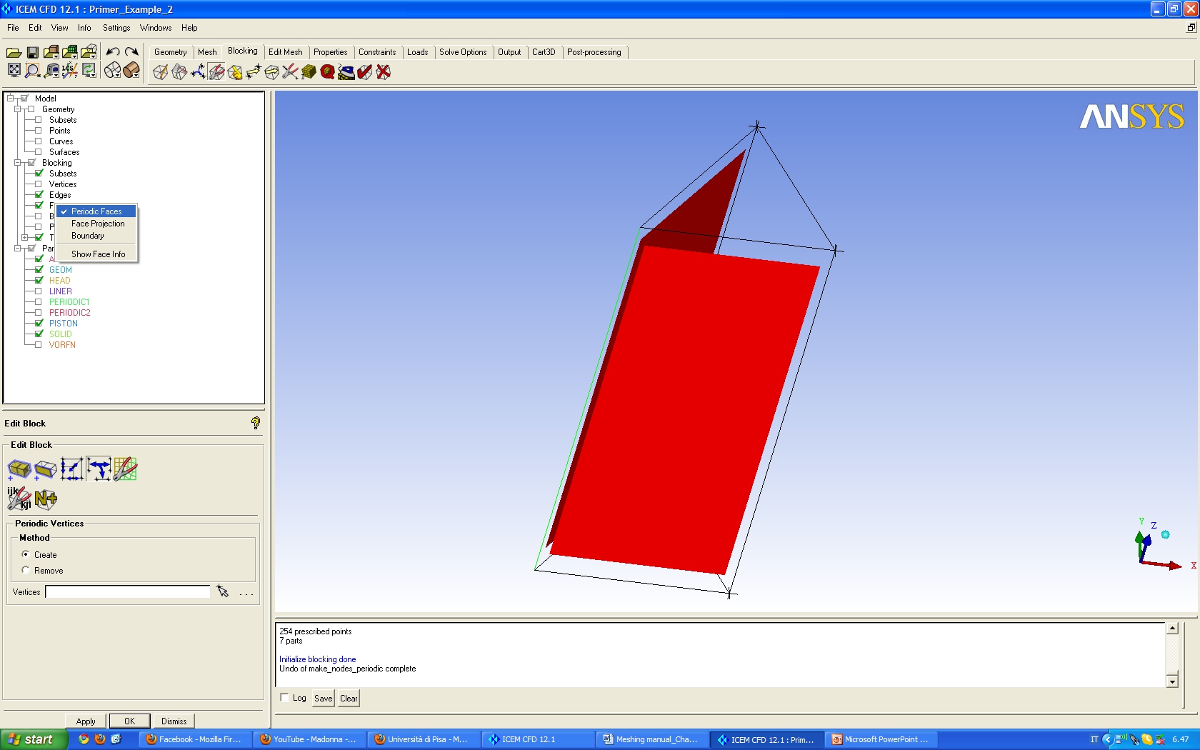
Fig. 2.13 Periodic faces
Step 5: Splitting the block
Differently from the Primer Tutorial 1 it is necessary to create different blocks to make the mesh following the piston bowl shape. From the Split Block Menu click on Split Block or press “s” on the keyboard and click in one of the edge normal to the splitting direction and repeat the operation following Fig. 2.14.
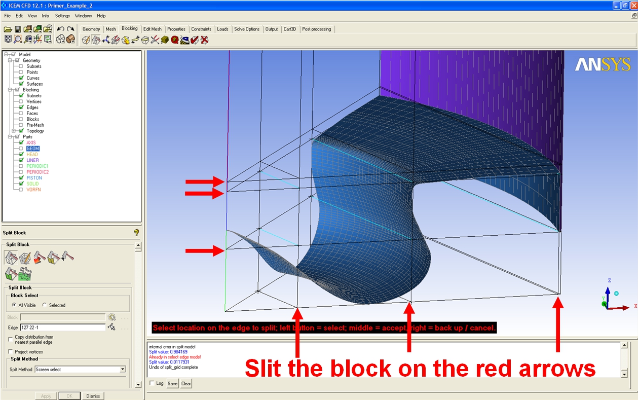
Fig. 2.14 Splitting the block
Step 6: Remove blocks
Display the Blocks right clicking on Blocks, Solid in the Display Tree menu, and remove the blocks shown in Fig. 2.15 using the Delete Blocks tool in the blocking menu or pressing “d” in the keyboard. To remove the connectivity between the active and deleted blocks display only the part VORFN select all blocks and delete them with the same command.

Fig. 2.15 Remove blocks
Step 7: Associate vertices to points
Use the Associate Vertex on entity Point from Associate in the Blocking menu and pick vertices and points as it is shown in Fig. 2.16.
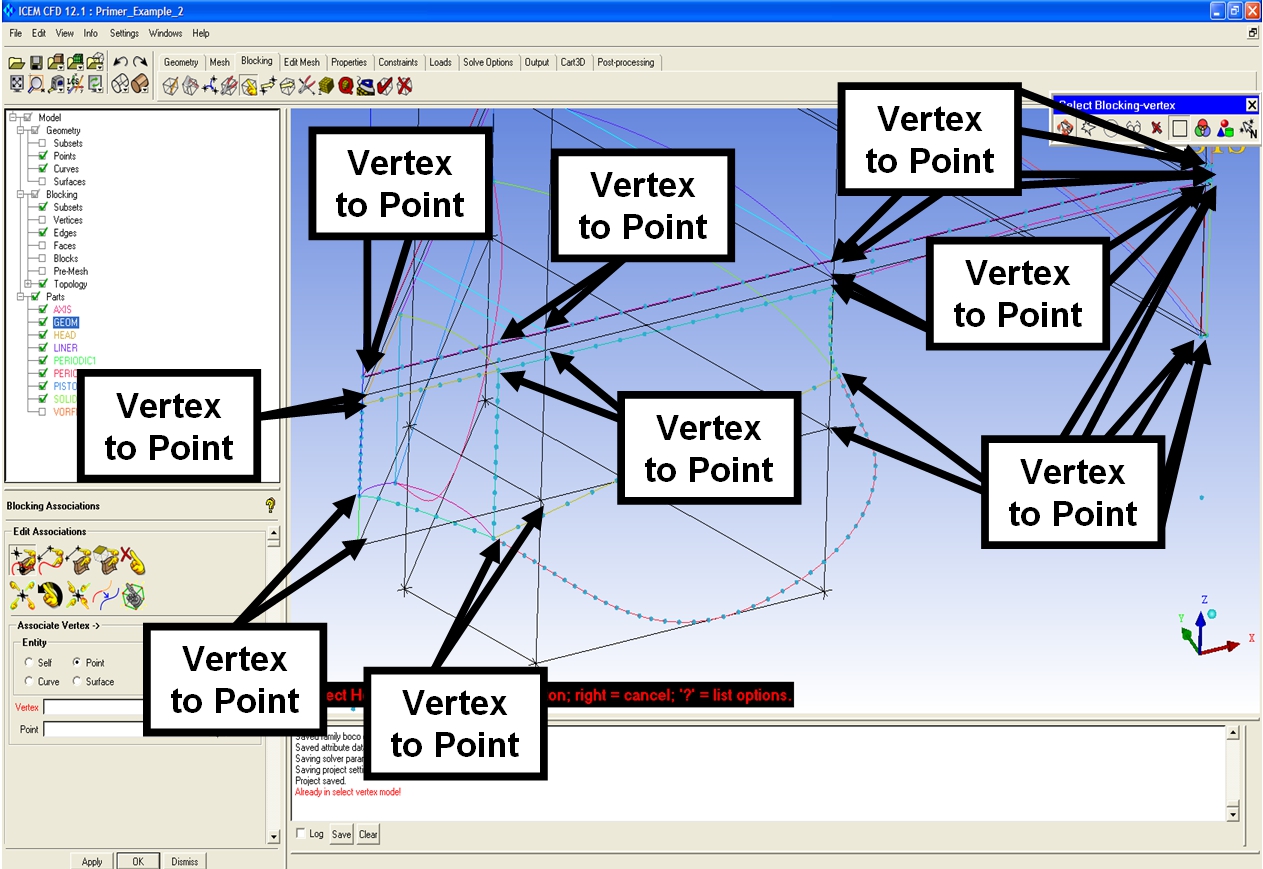
Fig. 2.16 Associate vertices to points
Step 8: Associate edges to curves
Press “p” on the keyboard and Associate Edges to Curves as it is shown in Fig. 2.17. Associate in the same way the edge in the head to the cylinder liner curve.
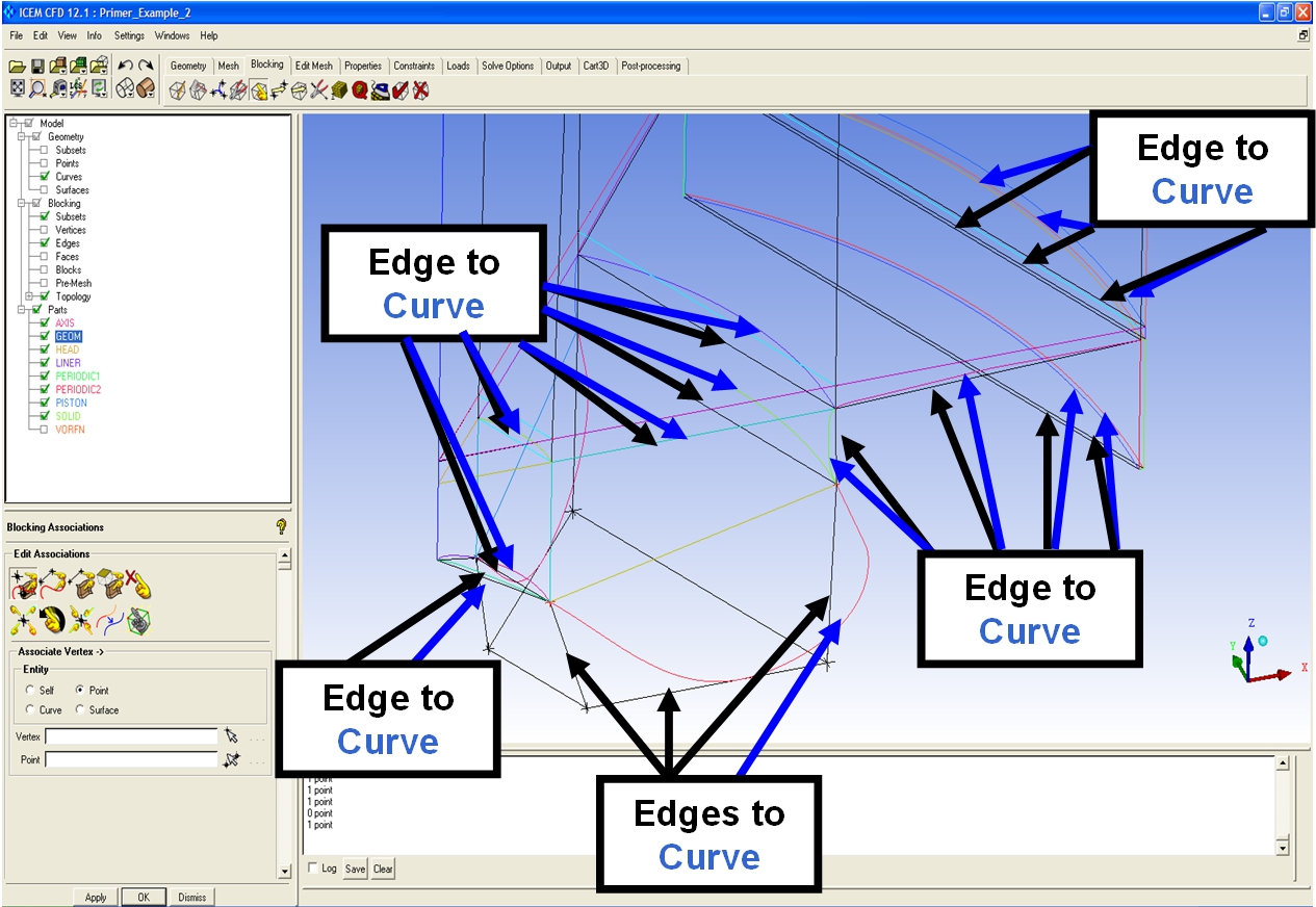
Fig. 2.17 Associate edges to curves
Step 9: Align the blocks
Right click on Blocking in the Display Tree menu and select Index Control, in the Index Control Window display the blocks from 4 to 5 in the k direction. In the Move vertices menu select the third option Align Vertices and select as it is shown in Fig. 2.18 the Edge direction and the Reference vertex. Select then XY in Move in plane anthen Apply. Press then reset in the Index Control Window to display all the blocks again.

Fig. 2.18 Align the blocks
Step 10: Move the bowl vertices
Move the two vertices on the bowl as it is shown in Fig. 2.19 using the Move vertex tool (or press “m” on the keyboard) with the Single Method.

Fig. 2.19 Move the bowl vertices
Step 11: Edges subdivision
In Blocking menu, Pre-Mesh parameter, Edge Parameter: select one edge in each direction xyz for each block direction, activate the Copy Parameter To all parallel edge, insert an appropriate number of nodes for each edge direction to obtain the mesh like in Fig. 2.20.
Step 12: Link edges shape
Some of the edge in the circumferential direction are not projected in any curves therefore the mesh distribution is not properly assigned (Fig. 2.21). Use the Link Edges tool in the Edit edge menu to copy the edge distribution from a projected edge. Select the edges as shown in Fig. 2.22. After this step the meshing process is completed and the final mesh is shown in Figs. 2.23 and 2.24.
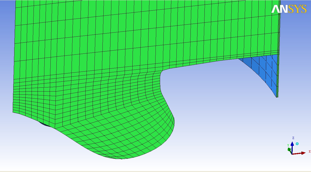 Fig. 2.20 Edges subdivision |
 Fig. 2.21 Mesh before linking the edges |
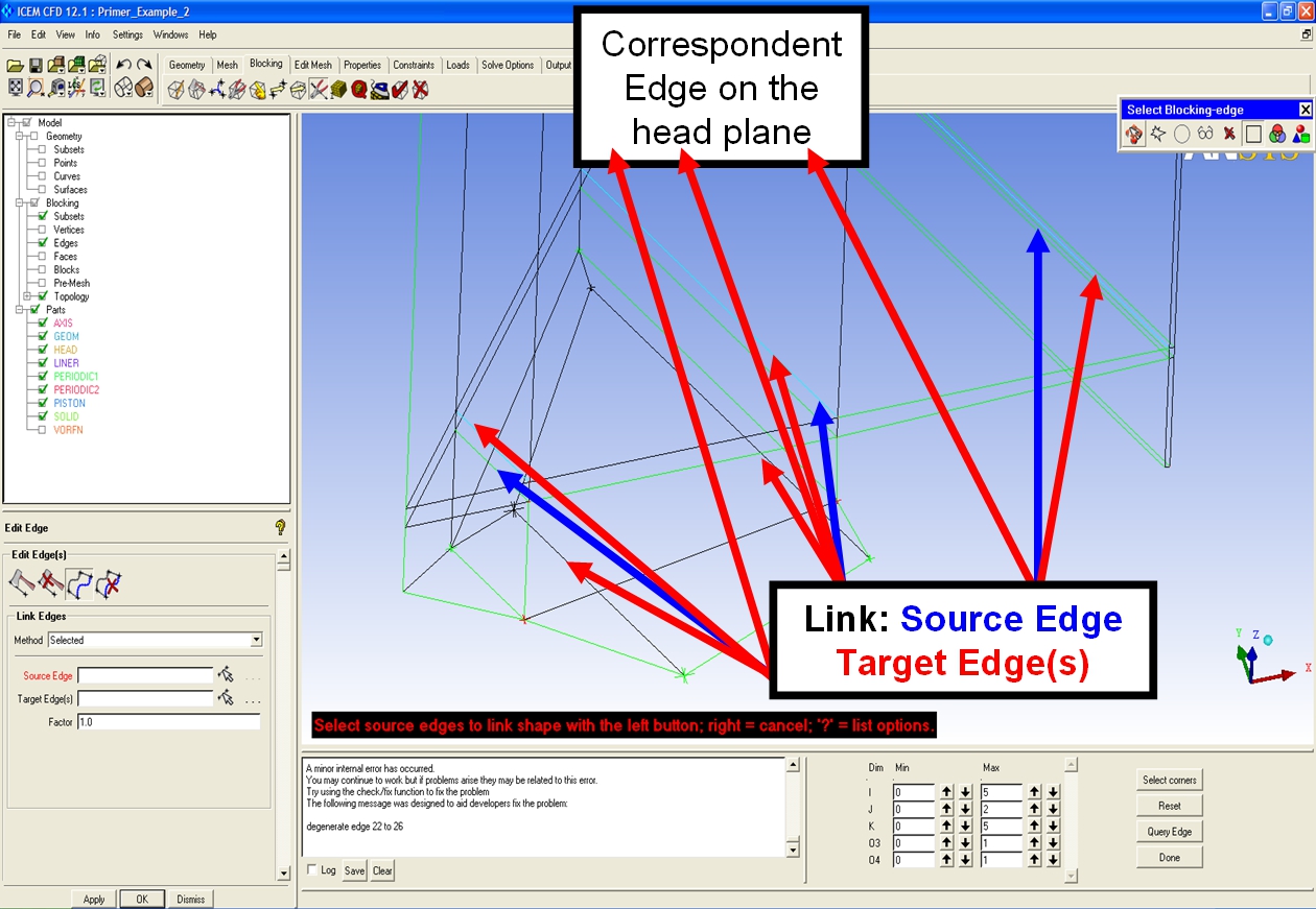
Fig. 2.22 Link edges shape
 Fig. 2.23 Final mesh front view |
 Fig. 2.21 Mesh before linking the edges |
![]()
![]()

