

Section 2.1. Geometry creation
The geometry is in general imported with points that defines the piston profile like in “iprep” for Kiva. The required points are listed in the file “Chapter_2_Input_Points.txt”.
 Download "Chapter_2_Input_Points.txt"
Step 1: Import the points
From the Create point tool in the geometry menu, use the Screen Select and then click on more beside the Select location arrow and a List Editor window will open, as it is shown in Fig. 2.2.
Right click on file open, browse the file “Primer_Example2_Points.txt” and click on open, Ok on the “Accept the changes made within ICEM CFD” window and then apply on the Create point window.
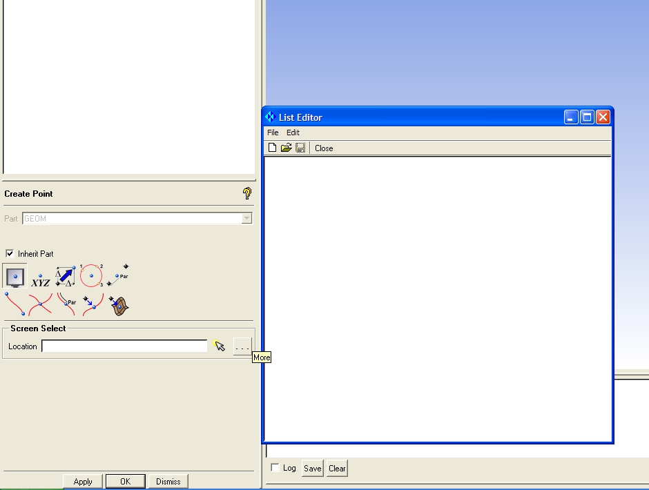 Fig. 2.2 Import the points |
 Fig. 2.3 Imported points |
Step 2: Create the lines
Create a spline in the bowl line From Points in the Create/Modify Curve menu by clicking on the points from the lowest one in the axis to the corner point that separates the bowl region from the squish region as in Fig. 2.4. Repeat the same operation for the piston line on the squish region, and then create straight lines with same command clicking in the first and last point to obtain all the curves shown in Fig. 2.5.
 Fig. 2.4 Creating the bowl line |
 Fig. 2.5 All lines |
Step 3: Create the surfaces
Create surfaces with the Surface of Revolution tool in the Create/Modify Surface menu. In the Surface of Revolution parameter insert 0 for Start Angle, 51.428571 (sector for a 7 hole injector) for the End Angle, select the top and bottom point of the axis for the Axis Points and select all the curves of Fig. 2.5 except the axis curve. The result of this step is shown in Fig. 2.5.

Fig. 2.5 surfaces creation
Step 4: Create the 2 periodic surfaces
Create two points with the coordinates 0 0 0, 4.1 0 0 using the same method of Par 1.1., and then a Simple Surface with the From 4 points method and click on the two new points and the two points on the head. Copy the surface using the Transformation Tools with the Rotate option, activating the radio buttons Copy and Angle inserting 51.428571, and selecting Z in Rotation Axis.
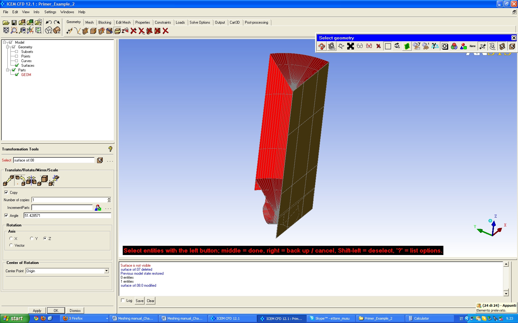
Fig. 2.6 periodic face creation
Step 5: Create geometry parts
Right click on Parts on the Model Tree and select Create Part, insert the name AXIS and select the axis line. Create then the parts PISTON, HEAD, LINER, PERIODIC1 and PERIODIC2 and assign the relative surfaces as shown in Figs. 2.8 and 2.9.

Fig. 2.7 Create the AXIS Parts
 Fig. 2.8 PERIODIC1, PERIDIC2, and HEAD parts |
 Fig. 2.9 PISTON and LINER parts |
![]()
![]()

